RGB Values/LED Sensor
- Get link
- X
- Other Apps
RGB
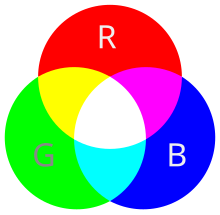
RGB stands for Red, Green, and Blue, the three primary colors used in digital color systems. Each color is assigned a value from 0 to 255, indicating its intensity. In the RGB model:
- Red (R) value ranges from 0 (none) to 255 (full intensity).
- Green (G) varies similarly.
- Blue (B) follows the same range.
- Red (R) value ranges from 0 (none) to 255 (full intensity).
- Green (G) varies similarly.
- Blue (B) follows the same range.
Colors are defined by a combination of these three values (R, G, B). For example, black is (0, 0, 0), and white is (255, 255, 255). This system is used widely in digital displays and graphics to create a multitude of colors.
LED Sensor

here's a list of components used in the picture:
- Arduino Uno
- Breadboard
- Jumper Wires: Wires used to connect components on the breadboard.
- Potentiometer
- LED: A light-emitting diode, indicating power or other statuses.
The photo shown above shows that there's a Arduino Uno connected to a board, called a breadboard, for testing out electronic circuits. Some colored wires link everything together. There's also a potentiometer to control things like volume, and an LED that turns on to show the circuit is working.
In this video, I'm demonstrating how it works.
Footnote
https://upload.wikimedia.org/wikipedia/commons/thumb/9/91/Venn_diagram_rgb.svg/220px-Venn_diagram_rgb.svg.png
https://www.developmenttools.com/rgb-color-codes/
https://en.wikipedia.org/wiki/RGB_color_model
- Get link
- X
- Other Apps


Comments
Post a Comment